HomeSmith Trainwreck: Bottom Feeders

Joined
Jul 25, 2017
Messages
1,164
Reaction score
6,907
Location
Arizona
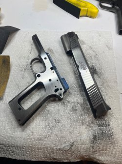
Here’s a picture I don’t see very often here…you get three guesses as to what the next project is, and the first two don’t count:

IMG_8112.jpeg

If you guessed a 1911 you’re partially correct.

There are two….


IMG_7629.jpeg

These are a pair of well used/abused full size Kimber Classics. Both are “Series 1” guns, so they don’t have the firing pin block.

What we know about them is that they both have lots of finish wear and are dirtier than a….never mind. Forum rules and all that. Let’s just say they’re dirty.

Down the rabbit hole we go…..
 
Register to hide this ad
I must say that the M-1911 and it's variants and variations are my favorite semi-auto pistols. Looking for forward to this project!
 
My plan for this project is to address safety and functional issues first, get both guns mechanically sound, and then to the cosmetic stuff last. If you're here for the refinishing portion, you have a couple of weeks to go do something else. ;)

A neat thing about this pair is that the serial numbers are exactly 20 numbers apart. One ends in 46, the other in 66. That's how I'll be referring to them.

As always, our adventure began with a function and safety check. Both guns were verified to be unloaded, and then the thumb safety, grip safety, disconnector, slide stop, magazine release and trigger pull were all tested. Number 66 passed all the tests and had a long crunchy trigger pull of 5 lbs. Number 46 passed the safety checks, but none of the magazines I tested would drop free and it had a very mushy 3.5 lb trigger pull.

Externally, both guns are scratched and rather worn but there doesn't seem to be any major damage that needs to be repaired.
Both slides are turning slightly purple, the screw heads for the grip panels are pretty mangled, and 66 has a hint of ugliness showing around the bottom of the right grip panel.

IMG_7633a.jpg
IMG_7636a.jpg
IMG_7638a.jpg
IMG_7640a.jpg

Both guns are just absolutely filthy at this point. I don't mean just dirty. Filthy. Like moldy crushed rice crispies mixed with toenail fungus and armpit hair filthy. These are probably some of the nastiest guns I've ever worked on. There was no lubrication as far as I could tell. Everything was riding on a layer of mung.

Ick.

The grip panel screws on 66 came out with a minimum of squeaking (!!!) but the grip panels themselves were stuck in place like they had been glued there. After prying them off by reaching in through the magazine well with a screwdriver, I learned where all the oil had gone: it was congealed behind the grip panels and they really were glued in place. They didn't pop off. They peeled off.
Here's how 66 looked underneath:

IMG_7641a.jpg

...and yes, that's a patch of rust.

IMG_7642a.jpg

Taking the slide off only exposed more gunk and nasty things. I think there's a feed ramp under there somewhere...

IMG_7643a.jpg

And the bore was fouled from chamber to muzzle:

IMG_7645a.jpg IMG_7646a.jpg


Number 66 seems to have a good heart though, because everything cleaned up reasonably well, including the bore and the rusty spot:

IMG_7653a.jpg
IMG_7648a.jpg

So far all I had done was a field strip cleaning. I could see down into the frame and what I saw was ugly enough that I decided to do that part later. We'll just do a top-end wipe down and go to the range so I can find out what needs to be fixed.

I'm glad that I looked at 66 first, because it prepared me for what 46 looked like inside. When I removed the mangled grip panel screws on number 44, three of the four grip screw bushings came out with the screws. I don't think the screws ever actually turned. This worked out well though, because the bushings helped peel the grip panels off the frame as they came out. The bushings need to come out anyway to refinish the frame so I don't consider this a tragedy at all.

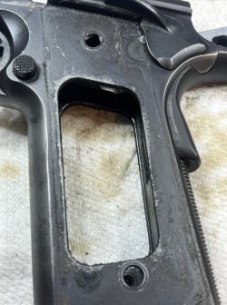
IMG_7668a.jpg IMG_7671a.jpg


I really don't want to re-live the experience of cleaning this gun, so I'm only going to give you one picture: a view of the trigger bar channel in the frame. I have no idea why the trigger pull on this gun feels like dragging a dirty sock through yesterday's lasagna.

IMG_7677a.jpg
 
Once both guns were clean enough that I would put them into my gun cases, I packed up a variety of magazines and headed to the range.

I told you 66 had a good heart….

IMG_7696.jpeg

In fact, the only issue I could find with 66 is that the extractor was just slightly too long and was leaving marks on the brass.

IMG_7698.jpeg

Four different brands of magazines fed flawlessly, empties were tossed about 8 feet at 4 o’clock, magazines all dropped free, and the slide lock functioned properly.

66 is a good gun. All it really needs is some love and attention.

46 turned out to be a snotty little brat though. I don’t know if the slide lock works because I couldn’t get through a full magazine without having a round jump ahead of the extractor.


IMG_7707.jpeg

The magazine release worked, but every magazine stuck in the gun.


IMG_7705.jpeg

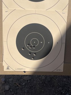
And to top it off, when it did go bang it shot consistently to the left. The one shot on the X-ring was from me holding off to the right.


IMG_7701.jpeg

It was about then that I noticed that 46’s front sight was shifted to the right. Compare the amount of metal visible on each side inside the dovetail.


IMG_7704.jpeg

At least now I knew where I was starting from. BTW will have to wait for his dual-wielding picture until I can make 46 run long enough to do it.

Next up will be a trip deep inside both guns…..
 
I decided to work on 66 first because we like each other. I'm still trying to work out living arrangements with 46.

The following is a pictorial essay on just how nasty a 1911 can be inside and still function. A neat data point: there was so much gunk in the frame that with everything else removed and the trigger in the frame by itself, it still took 6 ounces of pull on my trigger scale to move the trigger through the accumulated glop.

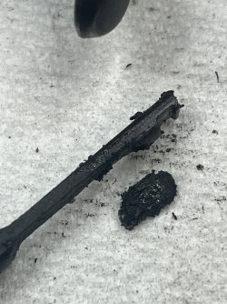
I'm also going to be that somewhere along the way a shell that was loaded too long got stuck, and as part of clearing the gun the shell was pulled apart and dumped powder into the guts of the gun, because that sure looks like unburned powder collected in the area behind the mainspring housing.

IMG_8109a.jpgIMG_8110a.jpgIMG_8111a.jpg
IMG_8116a.jpgIMG_8118a.jpg

The next step after taking it apart was to hose out the frame. Literally. I took it outside and used half a can of aerosol brake cleaner to blast most of the nastiness out.

I did this work the same way I approach Smiths: complete tear down, cleaning, inspection, and action job during the reassembly. The trigger is the last piece to come out and the first piece to go in, so that's where we started. The trigger channel was swabbed out with a qtip and a hand window file was used as a feeler to check for any rough spots. There weren't any, probably because the trigger had been "lubricated" with the equivalent of lapping compound for who knows how long.

IMG_8125a.jpg

Then, a magazine was used for a dual purpose: as a gauge to ensure that the trigger bow had enough width to allow the magazine to slide freely, and also to support the sides of the trigger bow while I polished them with 800 grit sandpaper.

IMG_8127a.jpg

The insides of the trigger bow were also polished with the 800 grit paper, being careful to always support the trigger to make sure nothing got bent.

IMG_8128a.jpg

The last step for the trigger was to stone the sloped face at the rear where the disconnector rides.

IMG_8129a.jpg

With everything clean and polished, the trigger would now slide completely out of the frame under it's own weight by simply tilting the frame.

Mucho better-o. One piece done. :oops:
 
After the trigger was done, the next piece to go in is the magazine release. The thing on the release that looks like a screw is not. Even worse than the nut-that-looks-like-a-screw that holds on a S&W thumb piece, this is a quarter-turn-fastener-with-a-stud-that-fits-in-a-slot-that-looks-like-a-screw. IMG_8132.jpegIMG_8130.jpeg

This is also the first of many springs that were replaced during this rebuild. Wilson Combat provided the kit.

IMG_8131.jpeg

This is an easy one to test. Either the magazine drops, or it doesn’t. It did.

The next piece is the disconnector, which was the cause of my one and only trip to a gunsmith with a paper bag full of parts. I was 16 and had taken apart my Dad’s 1911 without keeping track of how the pieces fit, and I couldn’t figure out how the trigger, disconnector, sear, and hammer went back together.

Experience is what you get right after you need it.

It’s been over 40 years, but I still remember “the flat goes on the flat, and the moon stands on its feet.”

Anyway, the disconnector has lots of places that can rub. The flat that bears against the back of the trigger, the angle where the middle leaf of the three-pronged spring sits, the round part that fits through the frame, the sides that potentially can rub on the sear. All of these areas get polished with a stone, and the center hole (where the pin goes) gets deburred with a needle file. That last one may not technically be necessary but I do it anyway, just like deburring the pin slot in a Smith hammer block.


IMG_8136.jpeg

The sear rides on the same pin as the disconnector, so it has to be prepped at the same time. I stone the sides of the inner slot where it fits around the disconnector, and then use a jig to clean up the sear surface. I have the Power Custom jig, the Harrison Design jig, and the Ed Brown jig. Of the three, the Ed Brown jig produces the “feel” that I prefer. All of them are good, just slightly different. I’m not going to go in to how it’s used…if you want to know, go to the Ed Brown website and follow THEIR directions.


IMG_8138.jpeg

The pieces all fit like this when you’re done.

IMG_8140.jpeg


The pin that holds these pieces together will fit in from either direction, but will only stay in if the head is behind the thumb safety.

Learned that one the hard way too….


IMG_8139.jpeg
 
The next piece to go in is the hammer. The hammer hooks are supposed to be .020” tall. That’s not an optical illusion in the picture…one side was taller than the other. They’re both at .020” now…

IMG_8142.jpeg

Tha hammer also told me that it was rubbing slightly on the frame. Some attention from a stone on the frame and sides of the hammer solved that.


IMG_8145.jpeg

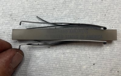
With the hammer in place, it was time to replace the three fingered leaf spring that tensions the sear, the disconnector, and the grip safety. This was also a Wilson Combat piece and it had a very different profile than the one that came out. The Wilson spring is on the bottom:


IMG_8149.jpeg

I decided to try the new spring as delivered to get a baseline. I’m pretty sure the grip safety leaf will need to be adjusted but we’ll see.

Before installing this spring, it’s important to radius the corners that bear against the other metal parts. A few zweep zweeps with the stone and we were ready to go in.


IMG_8150.jpeg
 
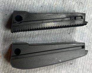
The three finger spring (hey - that sounds like a good name for a band :cool:) is retained by the mainspring housing. This pair of Kimbers (and every other factory spec Kimber I've ever seen) had flat, plastic mainspring housing. I get it. They're less expensive and do the job just fine.

I don't like plastic.

And I don't like flat mainspring housings because I tend to shoot low when I'm in a hurry.

So....Ed Brown to the rescue again. The arched steel mainspring housing changes the balance of the gun slightly and gives me a much more secure grip than the flat one.

IMG_8153a.jpg

But it didn't fit.

IMG_8156a.jpg

After a few test fits the frame told me where the problem was:

IMG_8157a.jpg

Here was a choice: do I modify the frame or the mainspring housing? The answer is always: change the cheaper, non-serial numbered part whenever you can. A few swipes from a file fixed us right up.

IMG_8159a.jpg

Before I could install the new arched mainspring housing, I needed to swap the internal components from the flat one and install the next Wilson spring upgrade. Here's a tip: make sure that there is a piece on both ends of the mainspring. The cone shaped one on the bottom sometimes sticks in the housing and if you don't know you need it, it's easy to assemble the housing without it. When that happens the gun will almost work most of the time. The indicators will be random light strikes and your mainspring housing pin walking out. The tip of the cone goes through a hole and engages the slot in the retaining pin. Without it the pin will eventually work it's way out.....but not while you're at the bench testing it.

IMG_8161a.jpg

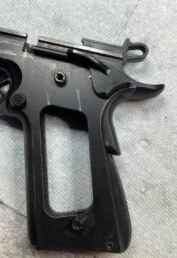
There's a tab on the bottom of the grip safety that fits under the mainspring housing, so that piece also has to go in at the same time as the mainspring housing. This is the time to replace the plunger tube spring with the one from the kit. Grab your needle nose pliers and put a kink into the middle of the spring. This will keep the spring from going sproing the next time you remove the thumb safety. The big end goes towards the thumb safety.

IMG_8163a.jpg

The hammer has to be at full cock for the thumb safety to be inserted, but you don't want it there when you're installing the mainspring housing. Cock the hammer, position the grip safety, install the thumb safety (a dental pick works well for moving the retaining plunger out of the way), then lower the hammer before installing the mainspring housing.

This part of the assembly process requires me to use 3 hands and I didn't have an extra hand available for the camera. Sorry.

Here's our frame put back together:

IMG_8164a.jpg
 
Moving on to the slide, other than cleaning and replacing the firing pin spring with the one from the Wilson kit, all the activity here was centered around the extractor.

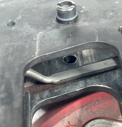
This extractor was leaving a mark in the fired brass and a quick test fit against a fired case showed me where to remove some material. I didn't remove much and I fully expect this to be a multi-part process, eventually sneaking up on the right length. I know I'm going to be changing the extractor tension also and that may have an impact (ha ha) here too.

IMG_8186a.jpg

This gun fed and ejected just fine during our test fire session, but when I did the "shake test" (put an empty case under the extractor and shake the slide - the case should stay in place and not fall out) the extractor felt very tight. I was on my way to the garage to bend it slightly when I stopped and had a chat with myself.

"Hey Self, what the heck are you doing adjusting something that "feels" tight? Are you going to make it "feel" looser? How much? And aren't you the guy who spent an entire afternoon measuring rebound spring tension? What happened to that 'we are educated men' thing?"

I was going to do it that way because that's the way I've always done it. By feel. There has to be a way we can quantify that.....

Some googling turned up a tool made by Weigand Machine that would allow the use of a trigger pull gauge to check extractor tension. I didn't feel like waiting or paying $24.95 plus shipping, so I started rummaging around in the random hardware box in the garage. After a few minutes on the drill press I had this:

IMG_8198a.jpg

How does it work? With the slide off and the extractor in place, the empty case is placed into the slide so that the hook sticks out the ejection port and the case is at the very bottom of the extractor. A trigger pull gauge is hooked to the hook and the case is pulled into the extractor very slowly, noting the amount of tension required to do so.

IMG_8208a.jpg

How much tension is correct? I have no freakin idea. This is version 1.0 of the tool and I have no data to use.

The instructions for the Weigand tool mentioned a range of 16 to 24 ounces, so I measured how much tension was needed to seat the empty case with the extractor in it's current state.

4 pounds, 2 ounces. (Bob Uecker voice: "Just a bit outside")

IMG_8204a.jpg


Yep, that might be a bit much. After some careful straightening of the extractor our tension was 22 ounces - on the high side of the range in the Weigand instructions. Is that the right number? No clue. It still passes the shake test, so I'll try it at the range and find out.

IMG_8205a.jpg
 
Last edited:
I'm not a fan of full length guide rods in 1911's. They make the gun require a tool for takedown and they remove the ability to rack the slide by placing it against a table or the heel of your boot. I'm not an operator who operates operationally but I do carry a 1911 quite often and that last bit is important to me. So....

IMG_8166a.jpg

No, there isn't any benefit to mixing stainless and blued parts here. It's what I had on hand. Coupled with an 18.5 lb recoil spring from our Wilson kit, these pieces were used for the final assembly and the full length guiderod went into the spare parts bucket.

A couple of flea-bay grip panels replaced the sticky-icky rubber grip panels that had to be peeled off earlier, along with a set of new hex head grip screws (by Wilson again) because the mangled screws looked like <insert forum friendly word here>.

IMG_8176.JPG

Now it's time to dig into the other gun....
 
Minor tip on the disconnector: the flat plate that engages the trigger bow has sharp corners at the top where the lower legs of the sear go past. Very slightly breaking those edges (front and rear) makes the sear's movement cleaner.
 
I thought that 66 was the dirtiest 1911 I had ever worked on, but that was before I opened 46 up.

The procedure used on the second gun was identical to the first with a few minor differences:

- more cleaning
- the replacement arched mainspring housing dropped right in
- all 4 grip screw bushings were replaced
- the front sight was drifted to the middle of the slide dovetail

Here are some highlights….

IMG_8297.jpeg

IMG_8315.jpeg

IMG_8316.jpeg

Extractor tension and disconnector tension were both set at 24 ounces, and the trigger pull came out at 4 1/2 pounds.


IMG_8318.jpeg


Here’s the pair before the range trip


IMG_8321.jpeg

My traveling sight adjustment tool kit went along so I could fine tune 46 at the range.

Both guns ended up reasonably well centered at 10 yards.


IMG_8346.jpeg

IMG_8353.jpeg

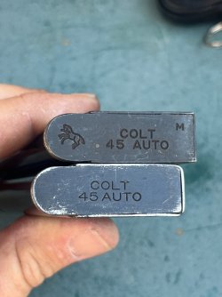
Roughly 100 rounds of 200 grain LSWC reloads were put through each gun with no issues except that 66 was still marking the brass with the extractor and these two magazines would not drop free from either gun.


IMG_8350.jpeg


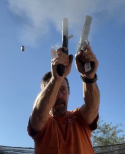
In order to do BTM’s party trick I set up two clean targets…


IMG_8355.jpeg

Then I moved my portable table to the 5 yard line, leaned my phone against my range bag, started recording video, and shot over the phone. I was sort of aiming by staring at point between the targets and using my peripheral vision to look at both sets of sights at the same time. 8 shots were fired at each target. I started getting the hang of it after the first few shots, so I guess this is something I need to practice more.

Here ya’ go BTM:


IMG_8358.jpeg

IMG_8359.jpeg

IMG_8360.jpeg

Left target:

IMG_8363.jpeg

Right target:

IMG_8362.jpeg
 
Last edited:
Now that both guns are reliable we can begin the cosmetic work. These are working guns so I’m not going for a museum quality restoration….this is “make it better” and not “make it perfect.”

As always, both guns were verified to be unloaded and then all the insides were moved to the outside and placed into labeled containers.


The plunger tubes on both guns were loose and would wiggle. Neither one was to the point of causing issues with the thumb safety or the slide lock, but if they got much looser that would begin to happen. I didn’t fix this during the mechanical phase because I knew they would have to come off during refinishing.

After verifying that I could actually find my plunger tube staking tool, I tried the recommended removal method of putting a piece of wire through the tube and using vise grips to pull the piece off of the frame.


IMG_8458.jpeg

This gave me two pieces of broken wire.

Three times.

Method 2 was to use an old Allen wrench and a precision prying implement (a screwdriver). This popped both tubes off easily and may have even left them in condition to be reused. I was planning on replacing them but if they can be reused it will be a bonus. Every little bit of margin helps.


IMG_8459.jpeg

IMG_8461.jpeg


Next, both frames had the slide rails taped so that they wouldn’t be touched during the metal prep.


IMG_8485.jpeg

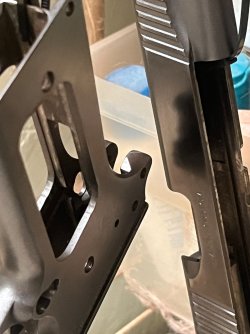
Kimber uses a multi-textured finish which has smooth, shiny flats and a matte finish on the rounded portions that looks bead blasted. I like that appearance when it’s new, but the matte portions are easily damaged and will scratch just by being looked at too hard. I don’t know what finish Kimber uses, but durable it is not.

My plan to try to improve on this was to scrub all of the surfaces hard with maroon scotch brite lubricated with a small amount of WD40, then to block sand the flats and rust blue everything.

The left side of 46’s slide required going down to 120 grit paper to remove a big scratch but other than that the sanding was uneventful. I didn’t do any file work and only removed imperfections that could be block sanded away. I made the decision that a few minor imperfections under the finish were preferable to wavy flats. I suppose I could have taken everything to the shop and used the surface grinder to make everything perfectly flat, but that would have added 6 hours to the project without a big return.

I think they came out ok.


IMG_8497.jpeg

At the moment number 66 has had three rust cycles and 46 had had two. I’m going to do 4 cycles at 100% solution strength to get a good solid base for the color before moving to the weaker solutions. Working around my job schedule, I expect the bluing process to take the rest of this week. Look for an update next weekend.

Here’s how 66 looks now:


IMG_8551.jpeg
 

Latest posts

Back
Top
OSZAR »